
Phase I Inspection of the Stay Cable System on the US 231 William H. Natcher Bridge over the Ohio River
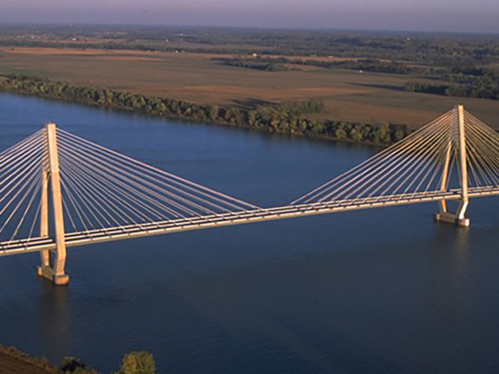
The US 231 William H. Natcher Bridge, spanning the Ohio River near Rockport, IN and Owensboro, KY was opened on October 21, 2002. At that time, it was the longest inland cable-stayed bridge in the U.S. Currently, it is the sixth longest bridge of that type. Since the completion of the four-lane section of US 231 from I-64 in Indiana, the traffic volume over the bridge has gradually increased. Work is underway to connect the bridge with the William H. Natcher Parkway to I-65. That will create an almost nonstop route that links I-64 and I-65 allowing traffic using those routes to by-pass Louisville. The main structure of the Natcher Bridge has a conventional two-tower layout employing diamond shaped pylons that are each 374 feet tall. Its main span is 1,200 feet long with two side spans that each measure 500 feet. The deck is 67 feet wide. The bridge has 96 stay cables that terminate at deck and tower anchorages. The stay cables are arranged in harp configurations with 48 cables connecting the deck with each of the pylons/towers on both the upstream and downstream sides of the bridge. The stay cables range in length from 170.17 feet to 606.87 feet. The cable diameters range from 5.51 inches to 8.58 inches. The cables contain between 18 to 61 steel strands (0.6-inch diameter) each of which contain seven 0.2-inch diameter wires. The strands were fabricated by greasing the wires and encasing them in polyethylene sheaths. High density polyethylene (HDPE) pipe/sheathing contains the strands to form the stay cables. Once the cables had been placed, the strands pre-tensioned, and HDPE piping assembled by welding, the interior of the HDPE piping was filled with a cementitious grout. According to the designer the HDPE pipes serve several functions:
•Provides additional layer of protection.
•Prevents water from entering the cables.
•Blocks UV light that can damage the strands sheath.
•Provides a smooth aerodynamic shape to the cable.
•Acts as a form for grouting.
The bridge has similar cable anchorage designs at both deck level and at the towers. In this system, the stay cable pipe is inserted into one end of a connection sleeve, with a transition pipe inserted into the other end. At the stay cable end of the connection sleeve, there is a reduced diameter fitting to accept the stay pipe. The report refers to that fitting as the “reducer”. A constant diameter fitting is attached to the other end of the connection sleeve to accept the transition pipe. That fitting is termed the “coupler”. Both of these fittings are butt-welded to the connection sleeve. Both fittings contain exposed helical wire wrappings on the inside faces that are connected at each end to external weld nipples. The stay cable pipe and transition pipe are thermally welded to the connection sleeve couplers and reducers (respectively) in slip fittings using a process termed electrofusion welding. In that process, an impressed current is run through the wires from an external power source attached to the weld nipples. The wires heat the HDPE plastic of the couplers and reducers causing them to melt locally and subsequently to fuse with the stay pipes and transition pipes, respectivelyon cooling. The heating wires are wound along the inner faces of the reducers (in the small diameter portions) and the couplers so as to create two separate welds running circumferentially and mate the slip-fitted pieces together. This provides some redundancy if one of the welds fails. A stay pipe is inserted into the small diameter portion of the reducer. At the end of the stay pipe there is an end fitting that narrows the diameter of the stay pipe and contains a steel bandthat acts as a reinforcement. Inside the connection sleeve, the strands emerge from the stay pipe, splay slightly and run down the length of the connection sleeve embedded in grout. Near the end of the connection sleeve, the sheaths are removed from the strands and the bare strands are inserted into tubes (separation sheaths) inside the transition pipe that run down to the anchor head. These tubes are wedged in countersunk holes in the anchor heads. The tubes are filled with grease prior to insertion of the strands to provide corrosion protection. The bare strands are run through the holes in the anchor head. On the exterior side of the anchor head, those holes are beveled. The strand tails are secured in tension by wedges inserted into beveled holes in the exterior face of the anchor head. According to the manufacturer, the anchorage assemblies were supplied with the tube portion pre-grouted tohold the tubes in place. At the anchorages, the strands are continually encased in HDPE starting with the stay cable, then the connection sleeve and finally the transitionpipe (which fits in a notch in the anchor head). The tower anchorages are a similar to the deck anchorages with shorter connections sleeves and the guide pipes embedded in the tower concrete. The anchor head is enclosed in a steel “protection cap” to prevent the strand ends/wedges/and back face of the anchor head from direct exposure to the atmosphere. Those items are coated with a grease intended to provide corrosion protection .The constant section piping, including the stay cables, connection sleevesand transition pipes are coextruded with a thin outer white layer of HDPE and an inner layer pigmented with carbon black. The stay piping has helically wound HDPE ribbing attached to the white coextrudedHDPEwhich is intended to promote the piping shedding water to preclude wind-rain vibration problems. The couplers and reducers butt-welded to the connection sleeve pipes are made from solid white HDPE pipe and are probably made by injection molding. The transition pipe is made from three pieces: an extruded pipe of solid carbon black pigmented HDPE, a molded transition piece and a coextruded pipe similar to the pipe segments of the connection sleeves. The pieces are assembled by butt-welding. The only part of the transition pipe exposed to the atmosphereis a short segment of the coextruded pipe.